DIAS Extension: SAE J1939 Option
Introduction to SAE J1939
Society of Automotive Engineers standard SAE J1939 is the vehicle bus recommended practice used for communication and diagnostics among vehicle components. Originating in the car and heavy-duty truck industry in the United States, it is now widely used in other parts of the world. SAE J1939 is a higher-layer protocol (e.g., an add-on software) that uses the CAN Bus technology as a physical layer. In addition to the standard CAN Bus capabilities, SAE J1939 supports node addresses, and it can deliver data frames longer than 8 bytes (in fact, up to 1785 bytes).
Since DIAS’s demonstrator vehicle is a Ford Otosan truck that follows SAE J1939 standard, it is necessary for KUKSA to adapt the standard.
The normal DBC file is used to apply identifying names, scaling, offsets, and defining information, to data transmitted within a CAN frame. The J1939 DBC file is designed to serve the same purposes but aiming at data transmitted within a Parameter Group Number (PGN) unit. This is due to the fact that some data frames are delivered in more than one CAN frame depending on the PGN’s data length in J1939.
To simply put, one can take a look at one PGN example. The following PGN-65251 information is captured in the official SAE J1939-71 documentation revised in 2011-03 (PDF Download Link).

PGN-65251 defines “Engine Configuration 1 (EC1)” and consists of 39 bytes as stated in “Data Length”. This means that to receive the complete information of PGN-65251, at least 6 CAN frames are required when considering the length of a single CAN frame is 8 bytes:

- A Transfer Protocol Broadcast Announce Message (TP.BAM) is used to inform all the nodes (e.g., Raspberry-Pi) of the network that a large message is about to be broadcast and defines the parameter group (The Target PGN) and the number of total packets to be sent. After TP.BAM is sent, a set of TP.DT messages are sent at specific time intervals.
- A Transfer Protocol Data Transfer (TP.DT) is an individual packet of a multipacket message transfer. It is used for the transfer of data associated with parameter groups that have more than 8 bytes of data (e.g., PGN-65251: 39 bytes).
For example, one TP.BAM and three TP.DT messages would be sent to deliver a parameter group that has more than 20 bytes (PGN-65260) as illustrated below:

There are a lot of concepts defined in the SAE J1939 documentation that are required to conform the J1939 transport protocol. One can look into the documentation to understand the concepts in depth. However, the general premise is simple: Raw CAN frames are processed to produce PGN data that should be decoded into CAN signals consumed by an in-vehicle application. Having said that, finding an existing J1939 library that can convert raw CAN frames to PGN data should be the first step. Since dbcfeeder.py is written in Python, it makes sense to choose the library written in the same language.
The Python J1939 package converts raw CAN frames to PGN data and makes the data available for use. The following figures compare two scenarios where dbcfeeder.py reads CAN signals without and with J1939.
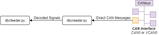
Without J1939, dbcfeeder.py receives decoded CAN singals through dbcreader.py that reads raw CAN frames directly from a CAN interface (e.g., can0 or vcan0).
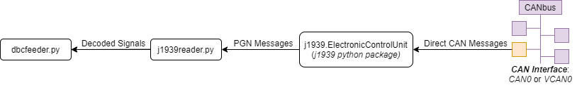
With J1939, dbcfeeder.py receives decoded CAN singals through j1939reader.py (source) that reads PGN messages from the j1939.ElectronicControlUnit (ECU) class of the python j1939 package that converts raw CAN frames to PGN data.
The j1939.ControllerApplications (CA) class from the python j1939 package is a superclass of j1939Reader.J1939Reader and utilizes the ECU class’s functionalities to derive PGN data.
At the time of writing this documentation, the following features are available from the python j1939 package according to here:
- One ElectronicControlUnit (ECU) can hold multiple ControllerApplications (CA)
- ECU (CA) Naming according SAE J1939/81
- Full support of transport protocol according SAE J1939/21 for sending and receiveing
- Message Packaging and Reassembly (up to 1785 bytes)
- Transfer Protocol Transfer Data (TP.DT)
- Transfer Protocol Communication Management (TP.CM)
- Multi-Packet Broadcasts
- Broadcast Announce Message (TP.BAM)
Implementation to j1939reader.py
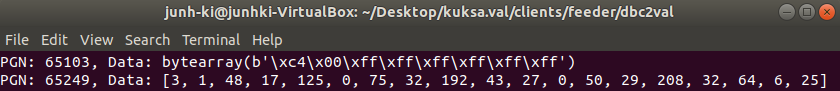
A sophisticated example of j1939.ControllerApplication that receives PGN messages from j1939.ElectronicControlUnit is already introduced here as OwnCaToProduceCyclicMessages. When running the OwnCaToProduceCyclicMessages class and a J1939 CAN log file together, the following messages can be shown on the OwnCaToProduceCyclicMessages’s terminal.
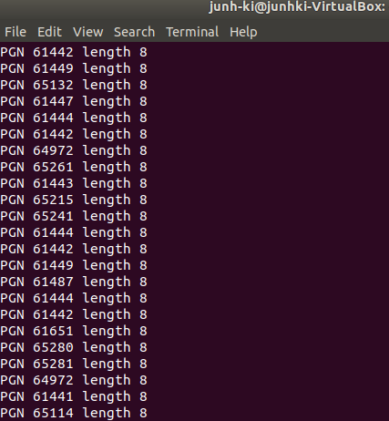
As shown above, each line prints out the number and the length of a PGN that has been read. These messages are produced from a callback function called OwnCaToProduceCyclicMessages.on_message.

As already mentioned, the general premise is that Raw CAN frames are processed to produce PGN data that should be decoded into CAN signals consumed by an in-vehicle application. Here we can divide the premise into three requirements:
- Getting PGN data
- Decoding PGN data into CAN signals
- Getting the decoded CAN signals available on the target in-vehicle application (e.g.,
dbcfeeder.py)
It is already possible to receive PGN data through OwnCaToProduceCyclicMessages (code). Also, some parts of dbcreader.py (code) can be reused for getting the decoded signals ready for the in-vehicle application.
j1939reader.py in dbcfeeder.py
1. dbcfeeder.py without J1939

In the case without J1939, dbcfeeder.py imports dbcreader.py and passes the required arguments when creating an instance of dbcreader.DBCReader. Then the dbcreader.DBCReader instance starts a thread by running start_listening() and receiving CAN frames through its connected CAN interface (cfg['can.port']).
2. dbcfeeder.py with J1939
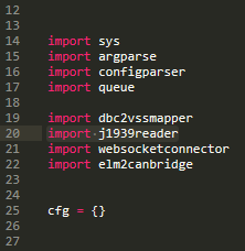
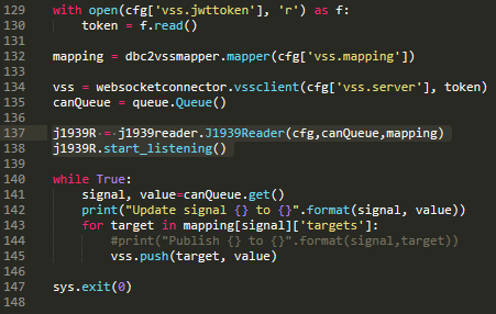
Likewise, in the case with J1939, dbcfeeder.py imports j1939reader.py instead of dbcreader.py and passes the required arguments when creating an instance of j1939reader.J1939Reader. Then the j1939reader.J1939Reader instance starts a thread by running start_listening() and receiving PGN data through a j1939.ElectronicControlUnit instance that is connected to the passed CAN interface (cfg['can.port']).
Decoding PGN Data with j1939reader.py
j1939reader.py (code) reuses OwnCaToProduceCyclicMessages and dbcreader.py for the requirement A and C with the add-on PGN decode functionality for the requirement B that is closely explained in the following.
1. Function: start_listening

start_listening creates a j1939.ElectronicControlUnit instance and connects it to the passed CAN interface (cfg['can.port']). Then the ECU instance adds the current j1939reader.J1939Reader (precisely, j1939.ControllerApplication inherited by j1939reader.J1939Reader) instance and starts a thread of it. After running start_listening, the ECU instance can start reading raw CAN frames from the connected CAN interface, convert them into PGN data and send the result to a callback function, on_message, of the j1939reader.J1939Reader instance.
2. Function: on-message
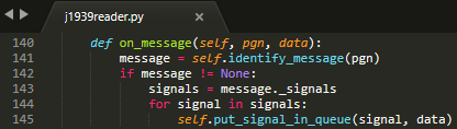
The callback function, on_message, receives PGN data and finds a corresponding CAN message in self.db by running identify_message. If the return value of identify_message is not None, it means that the observed PGN has the corresponding message and thus it iterates the list of signals of the message and decodes each signal and puts the result in self.queue by running put_signal_in_queue.
3. Function: identify_message

identify_message examines the database instance (self.db) that has been built with the passed DBC file (cfg['vss.dbcfile']) to get a message (cantools.database.can.Message) that corresponds to the observed PGN. Because PGN is the only available parameter that can identify what parameter group a CAN message is intended for, understanding how a CAN frame (especially CAN-ID) is structured is important so that the application can compare the observed PGN to a comparison message’s ID to confirm whether or not they match.
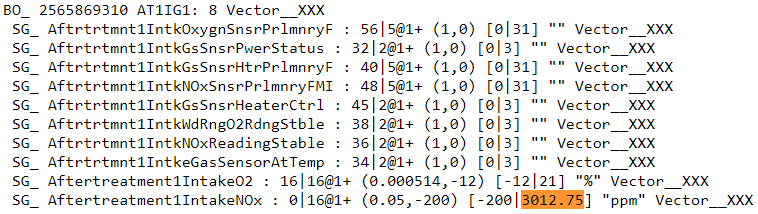
In the case of PGN-61444 (Electronic Engine Controller 1 / EEC1), it is (0x)f004 when 61444 is converted to hex. Therefore, identify_message should find a CAN message with an ID that contains f004 among the messages from self.db. The IDs of all messages in self.db are determined based on the passed DBC file (cfg['vss.dbcfile']). The following image (source) shows how a J1939 DBC file looks like.
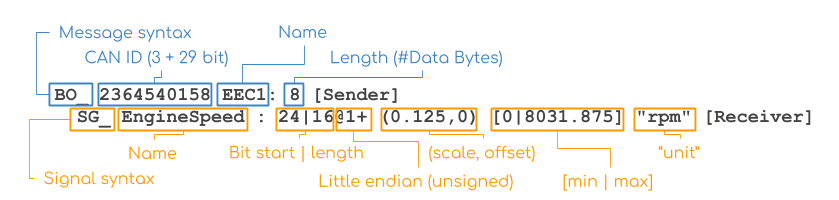
The needed information in the above image is CAN ID: 2364540158. It is (0x)8CF004FE When 2364540158 is converted to hex. To understand what exactly (0x)8CF004FE indicates, one can refer to the following image that explains the J1939 message format.

As described above, CAN ID consists of 29 bits in J1939. To express the value on a bit level, the binary conversion needs to be applied to (0x)8CF004FE, making it (0b) 1000 1100 1111 0000 0000 0100 1111 1110. With this, the following information can be derived.
| ID Form | Correponding Value of ECC1 |
|---|---|
| PGN | 61444 |
| PGN in hex | (0x) f004 |
| PGN in binary | (0b) 1111 0000 0000 0100 |
| DBC ID | 2364540158 |
| DBC ID in hex | (0x) 8cf004fe |
| DBC ID in binary | (0b) 1000 1100 1111 0000 0000 0100 1111 1110 |
Since the number of binary numbers is 32 (bits) making it bigger than 29 (bits), the first three binary numbers are omitted: (0b) 0 1100 1111 0000 0000 0100 1111 1110. With this and the message format image, the folloiwng information can be derived from the ECC1 message ID.
| J1939 Message Info | Binary | Decimal | Hex |
|---|---|---|---|
| 3 Bit Priority | (0b) 0 11(00) |
3 |
(0x) c |
| 18 Bit PGN | (0b) (00) 1111 0000 0000 0100 |
61444 |
(0x) f004 |
| 8 Bit Source Address | (0b) 1111 1110 |
254 |
(0x) fe |
As shown above, the decimal value of ECC1 message ID’s PGN is the same as 61444 which means that it is possible to confirm whether or not one of the CAN messages in self.db has the same value of PGN as that of the observed PGN. identify_message converts the observed PGN into a hex value and compare the value to the hex PGN value of each message in self.db. If the hex value of the observed PGN matches with that of the comparison message’s PGN, it means that the comparison message is what the observed PGN indicates and thus the message is returned.
4. Function: put_signal_in_queue

Once the target message is returned by identify_message, on_message iterates the list of signals in the returned message and puts each signal (cantools.database.can.Signal) with its calculated value in the queue (self.queue) that would later be used to feed kuksa-val-server by running put_signal_in_queue. In put_signal_in_queue, there are two scenarios. One is when the type of data is “list”, and the other is when the type of data is “bytearray” as shown below.
In the scenario where the data type is “list”, the size of data is more than a CAN frame’s maximum payload of 8 bytes (e.g., 39 bytes with PGN-65251) in which case data comes in a form of a list of decimal numbers. In this case, the start byte and the length of data should be calculated as each number represents a byte’s decimal value and the data access is done on 1 byte basis. For example, if the DBC file describes that the observed signal’s start bit is 16 (It starts from 0 in DBC files) and its length is 16, it means that the number of start byte is 2 (starts from 0) and the length of data is 2. Which means that the third and fourth numbers in the list express the observed signal’s value. With this information, decode_signal calculates the value of the observed signal with other attributes described by the DBC file.
In the other scenario where the data type is “bytearray”, the size of data is 8 bytes. In this case, the data access is done on 1 bit basis and the start bit and data length can be used without any processing as they are based on a bit level. With this information, decode_byte_array directly calculates the value of the observed signal with other attributes described by the DBC file.
Once the value is calculated, it checks whether the calculated value is bigger than the signal’s maximum or its minimum. If the value is out of the allowed scope of the signal, it is changed either to minimum or maximum before it is passed to the queue (self.queue).
- One can refer to here to find out all the available attributes from
cantools.database.can.Signal. This also depends on the target DBC file.
5. Function: decode_signal
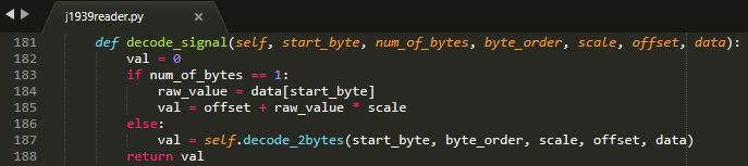
decode_signal is to calculate the value of the observed signal when the data access level is on a byte level in which case data comes in a form of a list of decimal numbers. If the number of bytes (data length) is equal to 1, the raw value can be directly extracted from data with the start byte number and the value of the signal can be calculated as follow:
![[value] = [offset] + [raw value] * [scale]](../_images/math/e1bb1c27c260c769eb4434b7d741c3cfc2cf54c3.svg) (Source)
(Source)
If the number of bytes (data length) is equal to 2, this means that two decimal numbers have to be aggregated to calculate the value of the signal which is done by running decode_2bytes.
6. Function: decode_2bytes
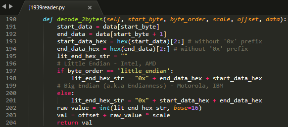
decode_2bytes calculates the value of the observed signal when the signal is decribed with two bytes. Because each decimal number in the list can be converted to hex (e.g., 16 = 0x0f) representing a byte, the aggregation of two decimal numbers is done after coverting them to hex.
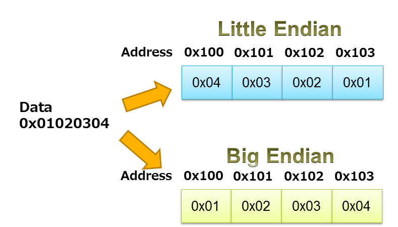
As described above, the aggregation depends on the byte order that is either “little_endian” or “big_endian”. According to here In J1939, the payload is encoded in the “little_endian” order from byte 0 to byte 7 while the bits in every byte are in the “big_endian” order as decribed in the table below.
| Bytes | 0 | 1 | 2 | 3 | 4 | 5 | 6 | 7 |
| Bits | 7..0 | 15..8 | 23..16 | 31..24 | 39..32 | 47..40 | 55..48 | 63..56 |
To get a raw value out of two hex numbers, they need to be arranged in the “big_endian” order before decimal conversion. Since the bits in every byte are already in the “big_endian” order, changing the order in a bit level is not required in any case. Therefore, in the case of “little_endian”, the start byte comes at the end whereas it comes at the beginning with “big_endian” which is highly unlikely in J1939, and the order of bits in each byte remains the same. Once the numbers are merged in a form of a hex number, the merged hex number is once again converted to decimal to describe the raw value. Then the same formula used in decode_signal is applied to calculate the result value.
7. Function: decode_byte_array
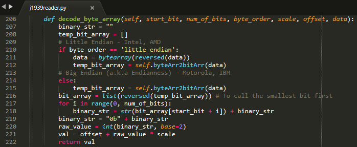
decode_byte_array is to calculate the value of the observed signal when the data access level is on a bit level in which case data comes in a form of a bytearray. As explained in decode_2bytes, the payload is encoded in the same way that bytes are in the “little_endian” order and the bits in every byte are in the “big_endian” order. If the byte order is “little_endian”, the bytearray is reversed first and then converted to a list of bits by running byteArr2bitArr to produce a binary string that is later converted to integer to get the raw value. Otherwise the same process is done but without reversing the bytearray which is highly unlikely in J1939. In any case, changing the order on a bit level is not required as well.

Running dbcfeeder.py with j1939reader.py
Clone the
junh-ki/dias_kuksarepository:$ git clone https://github.com/junh-ki/dias_kuksa.git
Navigate to
dias_kuksa/utils/in-vehicle/j1939feeder/and copyj1939reader.pyand paste it tokuksa.val/clients/feeder/dbc2val/wheredbcfeeder.pyis located.Install J1939 Python dependency:
$ pip3 install j1939
Come back to the
Homedirectory and install the wheel-package:$ cd $ git clone https://github.com/benkfra/j1939.git $ cd j1939 $ pip install .
In
dbcfeeder.py(kuksa.val - dbcfeeder.py Setup), any line that involves withdbcreader.pyshould be replaced to work withj1939reader.py.
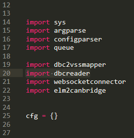
5-1. Import part:
# import dbcreader
import j1939reader
5-2. Reader class instance creation part:
# dbcR = dbcreader.DBCReader(cfg,canQueue,mapping)
j1939R = j1939reader.J1939Reader(cfg,canQueue,mapping)
5-3. start_listening function part:
# dbcR.start_listening()
j1939R.start_listening()
Make sure
kuksa-val-serveris up and running and a CAN interface (vcan0orcan0) is configured before runningdbcfeeder.py.Navigate to
kuksa.val/clients/feeder/dbc2val/wheredbcfeeder.pyis located, and command the following:$ python3 dbcfeeder.py -d vcan0 -j ../../../certificates/jwt/super-admin.json.token --dbc dias_simple.dbc --mapping dias_mapping.yml
- The following screenshots show what values are stored in
kuksa-val-serverat the end of playing log files (can0_otosan_can0-30092020andcan0_otosan_can2-30092020).

In the normal case, dbcfeeder.py is not able to read EngRefereneceTorque, EngSpeedAtIdlePoint1 and EngSpeedAtPoint2. These three signals belong to PGN-65251 (Engine Configuration 1 / J1939) and are delivered with a TP.BAM with multitple TP.DT messages since the size of the message is bigger than 8 bytes (size of 1 CAN frame = 8 bytes). Also, the value of Aftertreatment1IntakeNOx is 3076.75 which is not correct considering it is bigger than the signal’s maximum value in the DBC file as shown below.
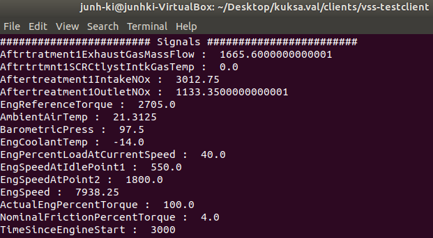
Now not only dbcfeeder.py with j1939reader.py is able to read these signals but also the value of Aftertreatment1IntakeNOx appears to be at the signal’s maximum and the other signals’ values are different from the case without J1939 as shown above. This is due to the fact that dbcfeeder.py has followed the J1939 standard when reading signals from CAN and all the values here are valid as they appear within their designated scope in the DBC file.